全部商品目录
产品中心
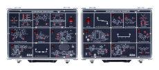
GRF-3300 Series RF射频教学系统- 详细介绍:
Designed for wireless frequency range applications
Includes a 880MHz Digital PLL and 2.4GHz microstrip line filter circuits
Training for the Voice Communication System
Demonstrates the applications and measurements for using spectrum analyzers in communication instruments
Instructional theory and hands-on experiments for each chapter covering topics in RF systems
Designed for the application of the RF Transmitter and Receiver systems
Specific RF circuit characteristics & PCB Layout on each module
Training system covering 22 modules, and over 50 experiments
|
Training Contents |
|||
|
Sections |
Theory |
Experiment |
Related Applications |
|
The Fundamentals |
Impedance matching network: L-type, π-type, T-type |
Theory explaining |
RF Component Test |
|
Antenna |
Antenna parameter, antenna structure, antenna type |
Frequency response |
Antenna Design |
|
Attenuator |
Attenuator parameter, attenuator type, attenuator design |
Attenuation characteristics |
When the Signal is Too Big |
|
Low Noise Amplifier |
LNA parameter, 1dB compression point, LNA structure |
Input and output return loss, amplifier gain, 1dB compression point |
Small Signal Enlarged |
|
Preamplifier |
Preamplifier type, preamplifier structure |
Input and output return loss, amplifier gain, 1dB compression point |
Small Signal Enlarged |
|
Power Amplifier |
Power amplifier frequency characteristics, bias circuit, power amplifier parameter, power amplifier structure |
Gain flatness, 1dB compression point, fundamentals to harmonics ratio |
Power Enlarge |
|
Filter |
Filter parameter, filter structure: Butterworth, Chebyshev |
Input/output return loss, insertion loss |
EMI filter Design |
|
Mixer |
Mixer structure, mixer parameter, mixer type |
Conversion gain, 1dB compression point, isolation |
TV Tuner |
|
Phase Locked Loop |
PLL structure, frequency synthesizer, PLL controller, loop filter, design a PLL |
Frequency response/modulation |
Signal Generator |
|
Audio Processor |
Audio compression/decompression circuit |
Pre-emphasis, compression characteristics, expander and de-emphasis, decompression characteristics |
Wireless Microphone |
|
Modulation |
Design and implement a modulation circuit |
Frequency modulation |
Remote Controller |
|
Demodulation |
Design and implement an FM intermediate frequency demodulation circuit |
IF modulation, RSSI output |
Broadcasting |
|
Transmitter |
Transmitter parameter, transmitter structure |
Transmission spectrum |
Radio Set |
|
Receiver |
Receiver parameter, receiver structure |
Receiving signal spectrum, demodulation waveform |
Radio Set |
|
Voice Demo |
Combine with transmitter & receiver circuits |
Voice communication system |
VoIP |
|
Microstrip Line Filter |
Transmission line basics, stepped-impedance LPF, coupled line BPF, optimized HPF |
Insertion loss |
RFID |
|
POWER SOURCE |
|||
| AC 110V or 220V, 50/60Hz | |||
|
DIMENSIONS & WEIGHT |
|||
| GRF-3300S | 428(W) x 90(H) x 303(D)mm for Transmitter & Receiver, Approx. 8.4kg | ||
| GRF-3300K | 560(W) x 170(H) x 530(D)mm, Approx. 7kg | ||
|
Ordering Information |
|||
| GRF-3300S Package | Including Spectrum Analyzer GSP-830 + Tracking Generator(TG), RF Training System GRF-3300S | ||
| GRF-3300K Package | Including Spectrum Analyzer GSP-830 + Tracking Generator(TG), RF Training Kit Sets GRF-3300Kning Kit Sets, 22 modules (12 for receiver and 10 for transmitter systems) | ||
| GRF-3300S(*) | RF Training System, Two Systems (Transmitter and Receiver) | ||
| GRF-3300K(*) | RF Training Kit Sets, 22 Modules (12 for Receiver and 10 for Transmitter systems) | ||
| (*)All GRF-3300S/K experiments are based upon GSP-830, we can't guarantee the result almost has its similarity by using other spectrum analyzers of their kinds. | |||
电子负载与电源用水冷选项")
")
")

